Use vector artwork as the starting geometry, then adapt it to the CAD application’s supported formats.
PUBLIC KNOWLEDGE VIEWCAD / Scanning / Automation / how-to
SOURCE STATENew reference guidance; not a recovered test result
GOALRun the first test described in this guide and record the result for svg import, emboss, and engraving workflow.
EQUIPMENT
CAD / automation tool
Representative test model
Measurement or inspection method
STEPS
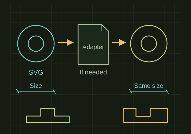
Clean the SVG with CAD-009 and set an explicit real-world size.
Check the destination’s current import list. If it cannot import SVG directly, convert clean paths to supported DXF/DWG geometry or use a CAD tool with an SVG importer.
Verify closed contours and the scale against a known dimension, then place the art on the intended face.
Extrude/add for embossing or subtract for engraving; print or machine a small detail sample before the full design.
TROUBLESHOOTING
Do not claim Shapr3D directly supports SVG unless its current format list says so. A 96-DPI or unit conversion mismatch can change size. Self-intersecting outlines often break extrusion.
THINGS TO WATCH FOR
Do not claim Shapr3D directly supports SVG unless its current format list says so. A 96-DPI or unit conversion mismatch can change size. Self-intersecting outlines often break extrusion.
RESULTA reopened export has the same dimensions and all text counters remain open.
 OPEN FULL SIZE ↗