Polycarbonate printing
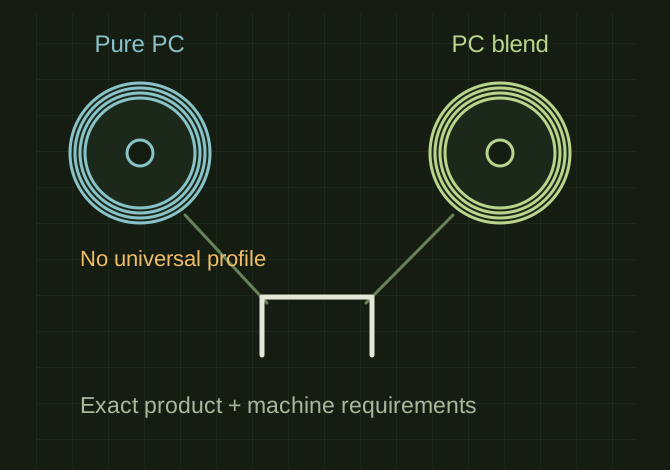
Polycarbonate can provide useful toughness and heat resistance for demanding housings and prototypes. Pure PC and easier-printing PC blends can have substantially different requirements. A spool marked PC is not enough information to assign a universal profile. Dry before printing. Prusa’s PC Blend drying example is 85°C for 5 hours, not a universal PC schedule. Confirm nozzle, bed, and chamber capability before slicing. If the spool requires temperatures above the machine’s rating, select a verified compatible material rather than lowering the required temperature and assuming equivalent results. Use a suitable release layer where required to protect the build surface.
A PC label is not a complete profile
 OPEN FULL SIZE ↗
- Products
- Pure PC / PC blends
- Verify
- Machine capability and exact formulation
- Sample
- Wall, corner and hole-fit coupon
TECHNICAL NOTES///
Polycarbonate can provide useful toughness and heat resistance for demanding housings and prototypes. Pure PC and easier-printing PC blends can have substantially different requirements. A spool marked PC is not enough information to assign a universal profile.
GOALRun the first test described in this guide and record the result for polycarbonate printing.
SETTINGS / STARTING POINT
PREPARATION / NOTES
Dry before printing. Prusa’s PC Blend drying example is 85°C for 5 hours, not a universal PC schedule. Confirm nozzle, bed, and chamber capability before slicing. If the spool requires temperatures above the machine’s rating, select a verified compatible material rather than lowering the required temperature and assuming equivalent results. Use a suitable release layer where required to protect the build surface.
EQUIPMENT
- FDM printer / slicer
- Slicer project
- Calipers or inspection method
MATERIALS
- Polycarbonate
STEPS
- Confirm printer, nozzle, plate, and material identity.
- Start from the recorded profile or the slicer default for that material.
- Print a small first-layer and geometry test before the full part.
- Inspect adhesion, dimensions, surface, supports, and failure mode.
- Save the successful project with temperatures, speeds, and revision notes.
TROUBLESHOOTING
- Moisture can cause bubbles and weak extrusion. Warping and layer separation are common obstacles. A visually acceptable part can still be poorly bonded. Thick solid regions may concentrate shrinkage; more infill is not an automatic fix. Finished-part heat performance depends on formulation, geometry, loading, and processing.
THINGS TO WATCH FOR
Moisture can cause bubbles and weak extrusion. Warping and layer separation are common obstacles. A visually acceptable part can still be poorly bonded. Thick solid regions may concentrate shrinkage; more infill is not an automatic fix. Finished-part heat performance depends on formulation, geometry, loading, and processing.
RESULTA short wall-and-corner sample followed by a hole-fit coupon, checking both bonding and dimensional change.
DEVELOPMENT HISTORY///
Imported as an independent manifest record; public copy keeps uncertainty visible.
SPECIFICATION///
RELEASED MATERIAL///
A short wall-and-corner sample followed by a hole-fit coupon, checking both bonding and dimensional change.
The record keeps what is known at this revision. Unfinished tests stay unfinished here.