PETG-CF printing
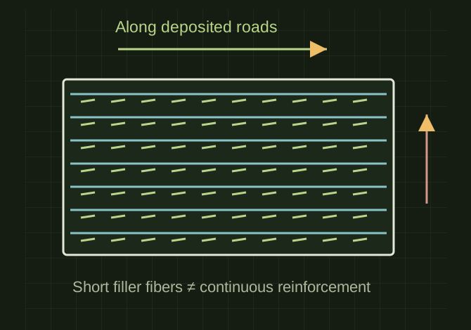
Carbon-fiber-filled PETG offers a matte finish and typically greater stiffness than the corresponding unfilled PETG. It is useful for housings, brackets, equipment mounts, and dimensionally stable prototypes. Increased stiffness does not automatically mean greater impact strength or stronger layer bonding. Dry to the product’s specification and store sealed. Orient loaded features so the principal load runs along deposited roads where practical rather than pulling layers apart. Increase wall thickness where fasteners load the part. Use the product’s actual density when estimating spool consumption and weight.
Stiffness and layer direction are separate
 OPEN FULL SIZE ↗
- Material
- PETG-CF
- Wear
- Abrasive filler
- Caution
- Stiffness does not establish impact strength or bonding
TECHNICAL NOTES///
Carbon-fiber-filled PETG offers a matte finish and typically greater stiffness than the corresponding unfilled PETG. It is useful for housings, brackets, equipment mounts, and dimensionally stable prototypes. Increased stiffness does not automatically mean greater impact strength or stronger layer bonding.
GOALRun the first test described in this guide and record the result for petg-cf printing.
SETTINGS / STARTING POINT
PREPARATION / NOTES
Dry to the product’s specification and store sealed. Orient loaded features so the principal load runs along deposited roads where practical rather than pulling layers apart. Increase wall thickness where fasteners load the part. Use the product’s actual density when estimating spool consumption and weight.
EQUIPMENT
- FDM printer / slicer
- Slicer project
- Calipers or inspection method
MATERIALS
- PETG-CF
STEPS
- Confirm printer, nozzle, plate, and material identity.
- Start from the recorded profile or the slicer default for that material.
- Print a small first-layer and geometry test before the full part.
- Inspect adhesion, dimensions, surface, supports, and failure mode.
- Save the successful project with temperatures, speeds, and revision notes.
TROUBLESHOOTING
- Fibers abrade nozzles and may clog small openings. A good-looking matte surface can hide poor bonding. Stringing and rough extrusion can still be moisture-related. Do not assume every automatic filament feeder supports abrasive filament. Contain dust during sanding or drilling.
THINGS TO WATCH FOR
Fibers abrade nozzles and may clog small openings. A good-looking matte surface can hide poor bonding. Stringing and rough extrusion can still be moisture-related. Do not assume every automatic filament feeder supports abrasive filament. Contain dust during sanding or drilling.
RESULTPrint a small bracket and hole-fit coupon; inspect layer bonding and fastener fit before producing the full part.
REFERENCES
provides a product example of 240–270°C extrusion and 0–40% part cooling; it does not verify Robert’s spool or FlashForge profile.
DEVELOPMENT HISTORY///
Imported as an independent manifest record; public copy keeps uncertainty visible.
SPECIFICATION///
RELEASED MATERIAL///
Print a small bracket and hole-fit coupon; inspect layer bonding and fastener fit before producing the full part.
The record keeps what is known at this revision. Unfinished tests stay unfinished here.