ASA printing and enclosure needs
ASA is useful for outdoor housings, covers, and fixtures because of its UV resistance and better heat tolerance than ordinary PLA. Its tendency to shrink while cooling makes enclosure conditions and bed adhesion central to success. Verify the installed enclosure and machine limits before selecting the profile. Let the enclosure stabilize using the normal bed preheat procedure. Keep extraction arranged so it does not blow cold air across the part. Provide ventilation appropriate for ASA emissions; an enclosure alone does not remove them. Orient and round large flat features to reduce concentrated corner stress where the design allows.
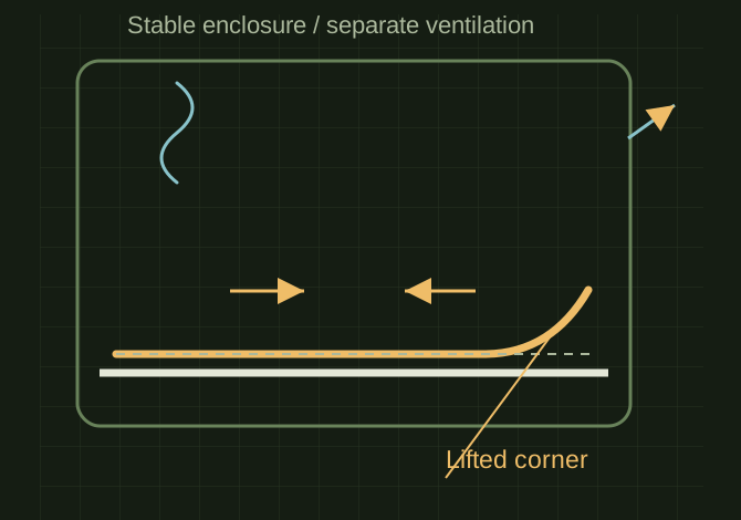
Corner lift in a cooling print
 OPEN FULL SIZE ↗
- Material
- ASA
- Failure signs
- Corner lift and layer splitting
- Environment
- Stable within machine limits
TECHNICAL NOTES///
ASA is useful for outdoor housings, covers, and fixtures because of its UV resistance and better heat tolerance than ordinary PLA. Its tendency to shrink while cooling makes enclosure conditions and bed adhesion central to success.
GOALRun the first test described in this guide and record the result for asa printing and enclosure needs.
SETTINGS / STARTING POINT
PREPARATION / NOTES
Verify the installed enclosure and machine limits before selecting the profile. Let the enclosure stabilize using the normal bed preheat procedure. Keep extraction arranged so it does not blow cold air across the part. Provide ventilation appropriate for ASA emissions; an enclosure alone does not remove them. Orient and round large flat features to reduce concentrated corner stress where the design allows.
EQUIPMENT
- FDM printer / slicer
- Slicer project
- Calipers or inspection method
MATERIALS
- ASA
STEPS
- Confirm printer, nozzle, plate, and material identity.
- Start from the recorded profile or the slicer default for that material.
- Print a small first-layer and geometry test before the full part.
- Inspect adhesion, dimensions, surface, supports, and failure mode.
- Save the successful project with temperatures, speeds, and revision notes.
TROUBLESHOOTING
- Lifted corners, horizontal splitting, or parts detaching indicate thermal or adhesion problems. More nozzle heat alone will not fix a cold chamber. Let the part cool gradually before opening the enclosure. Do not add unapproved heaters or cover cooling electronics to raise chamber temperature.
THINGS TO WATCH FOR
Lifted corners, horizontal splitting, or parts detaching indicate thermal or adhesion problems. More nozzle heat alone will not fix a cold chamber. Let the part cool gradually before opening the enclosure. Do not add unapproved heaters or cover cooling electronics to raise chamber temperature.
RESULTA small flat rectangle with corners, followed by a taller sample to check layer splitting.
REFERENCES
. Exact heat resistance and temperature requirements depend on formulation and test conditions.
DEVELOPMENT HISTORY///
Imported as an independent manifest record; public copy keeps uncertainty visible.
Connected the newer project records: 3DP-ASA-HOSE-001. Existing test limitations remain in place.
SPECIFICATION///
RELEASED MATERIAL///
A small flat rectangle with corners, followed by a taller sample to check layer splitting.
The record keeps what is known at this revision. Unfinished tests stay unfinished here.