Clear PETG printing
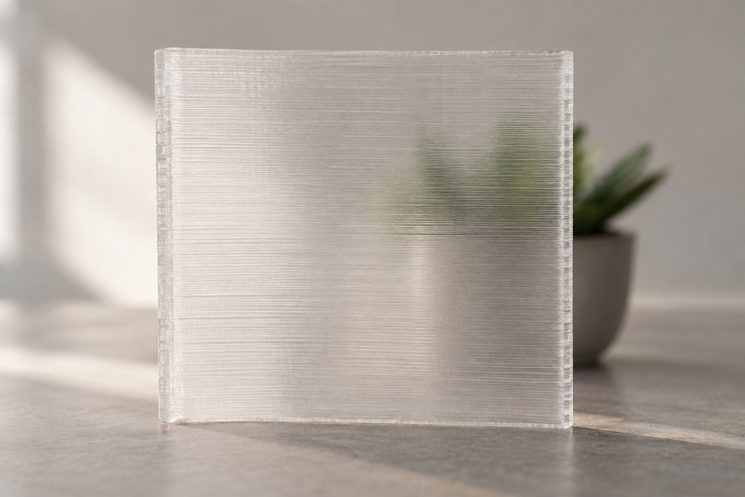
Clear PETG suits translucent covers, light diffusers, display pieces, and containers where seeing light or a rough outline through the wall is useful. Ordinary FDM prints scatter light at layer boundaries and internal gaps; clear filament alone does not produce glass-like transparency. Dry before optical tests. Prusa’s PETG example is 55°C for 6 hours; use the actual spool maker’s instructions. For a diffuser, test a thin hollow shell before adding infill. For a solid viewing section, compare a small 100% infill sample with consistently aligned lines against the ordinary profile. Do not promise transparency or raise flow blindly to eliminate gaps. Use a plate-approved release layer where required: PETG can bond excessively to smooth surfaces.
TECHNICAL NOTES///
Clear PETG suits translucent covers, light diffusers, display pieces, and containers where seeing light or a rough outline through the wall is useful. Ordinary FDM prints scatter light at layer boundaries and internal gaps; clear filament alone does not produce glass-like transparency.
GOALRun the first test described in this guide and record the result for clear petg printing.
SETTINGS / STARTING POINT
PREPARATION / NOTES
Dry before optical tests. Prusa’s PETG example is 55°C for 6 hours; use the actual spool maker’s instructions. For a diffuser, test a thin hollow shell before adding infill. For a solid viewing section, compare a small 100% infill sample with consistently aligned lines against the ordinary profile. Do not promise transparency or raise flow blindly to eliminate gaps. Use a plate-approved release layer where required: PETG can bond excessively to smooth surfaces.
EQUIPMENT
- FDM printer / slicer
- Slicer project
- Calipers or inspection method
MATERIALS
- PETG
STEPS
- Confirm printer, nozzle, plate, and material identity.
- Start from the recorded profile or the slicer default for that material.
- Print a small first-layer and geometry test before the full part.
- Inspect adhesion, dimensions, surface, supports, and failure mode.
- Save the successful project with temperatures, speeds, and revision notes.
TROUBLESHOOTING
- Bubbles, popping, and a frosted surface can indicate moisture. Stringing may also come from excess heat or retraction behavior. Low cooling can improve bonding but hurt bridges and overhangs. Infill remains visible through clear walls. Let the plate cool before removal.
THINGS TO WATCH FOR
Bubbles, popping, and a frosted surface can indicate moisture. Stringing may also come from excess heat or retraction behavior. Low cooling can improve bonding but hurt bridges and overhangs. Infill remains visible through clear walls. Let the plate cool before removal.
RESULTPrint two small identical wall samples at different cooling levels; compare clarity and bonding under the same light.
REFERENCES
, . Optical tests and build choices above are proposed experiments, not manufacturer guarantees.
DEVELOPMENT HISTORY///
Imported as an independent manifest record; public copy keeps uncertainty visible.
SPECIFICATION///
RELEASED MATERIAL///
Print two small identical wall samples at different cooling levels; compare clarity and bonding under the same light.
The record keeps what is known at this revision. Unfinished tests stay unfinished here.