Bayonet Cap / A Twist-Lock for a Simple Holder
I had a simple holder in Shapr3D and wanted a cap that attached outside it and held up over repeated use. I asked about threads and alternatives, then supplied the body's two diameters. The discussion proposed a three-tab bayonet closure. This is the design brief and its first dimensions, with the original holder screenshot; it is not a claim that the locking cap has been modeled, printed, or cycle-tested.
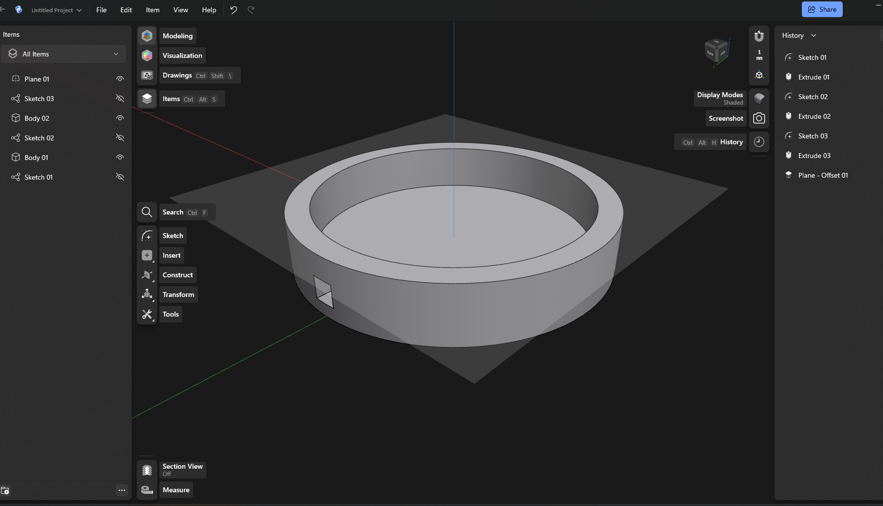 CAD-BAYONET-CAP-001
TECHNICAL NOTES///
A 60 mm inside diameter and 70 mm outside diameter gave this holder a starting point. The proposed lid uses three tabs and a short twist, with clearances and locking details still to be tested.
The question was practical: is there an easy way to make a threaded cap in Shapr3D, or another attachment that will hold up over time? The supplied holder made that a specific design problem.
The two confirmed dimensions are 60 mm inside and 70 mm outside. That gives a nominal 5 mm radial wall. The screenshot preserves the starting model, including its rim and side opening. It does not show a finished lid or a completed set of locking features.
The proposed alternative was a bayonet closure: lower a cap over tabs on the body, then rotate it so the tabs sit beneath retaining surfaces. Three tabs spaced 120 degrees apart were suggested. A stop, small detent, or ramp could be explored later, but none was shown as finished work or tested in use.
The first sizing suggestion used a 70.6 mm cap bore around the nominal 70 mm body. That creates 0.3 mm radial clearance before printing tolerances are considered. A 3 mm wall and top, and tabs 7 mm wide, 4 mm high, and 2 mm deep, were also proposed. These values belong to a trial design, not a proven tolerance chart.
The locking tracks still need engineering. Their depth must accommodate the tabs and leave enough material outside the track. The earlier suggested travel length and approximate twist angle were not a resolved geometric definition, so no final angle is specified here. Cap height, seating position, detent force, and the remaining wall thickness need to be checked together in a section view before a full cap is committed to print.
For the modeling approach, Shapr3D's circular Pattern tool can distribute separate tab bodies or sketch profiles around the holder axis. Matching cutter bodies can be patterned before subtraction to create repeated channels. This is more precise than describing the operation as patterning a finished cut feature, which is not the workflow shown in Shapr3D's bodies-and-patterns guide.
The suggested next experiment was a small mating test ring or cap section. Its job would be to establish clearance, engagement, and release force before printing the complete assembly. PETG was discussed as a candidate material, but no final filament, print settings, or endurance result was recorded. The project remains a measured starting point with a testable closure idea.
DEVELOPMENT HISTORY///
The user supplied the holder screenshot, asked for a durable alternative to external threads, and specified 60 mm ID and 70 mm OD.
Published the measured starting envelope and clearly labeled bayonet proposal; unresolved locking geometry remains explicit.
SPECIFICATION///
RELEASED MATERIAL///
The holder geometry and design request are documented. A three-tab bayonet and preliminary dimensions were suggested; the locking design and its durability remain untested.
The record keeps what is known at this revision. Unfinished tests stay unfinished here.