Fidget Spinner / Simplicity Wins
I wanted something that would spin freely and keep going after a flick. That small goal led through Shapr3D extrusion controls, smooth connecting arcs, bearings that felt stiff, and a question about putting N52 magnets around a printed housing. The result on the workbench is a white, three-lobed spinner with four bearings. The useful part of the project was working through those questions and coming back to a simple object I could actually make.
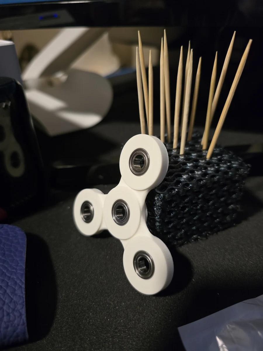 MDL-SPINNER-001
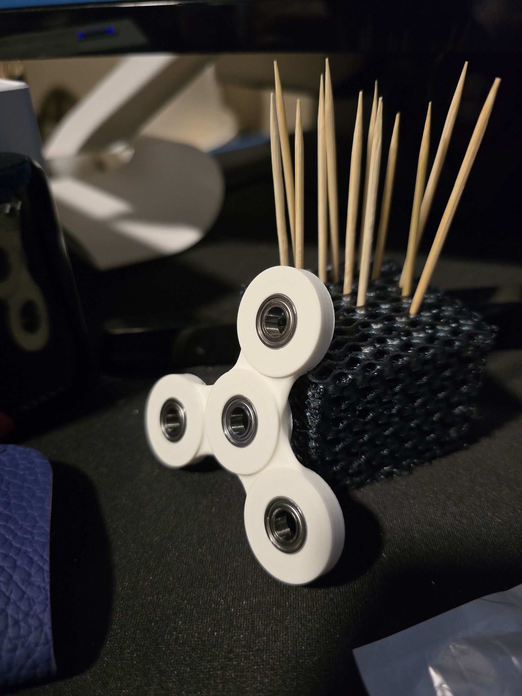 FINISHED BUILD / White printed spinner with one central bearing and three outer bearings. Supplied workbench photograph.Photograph supplied by Robert Hutchins. Orientation applied, resized for the web, and metadata removed. Full composition retained; no changes to the spinner.
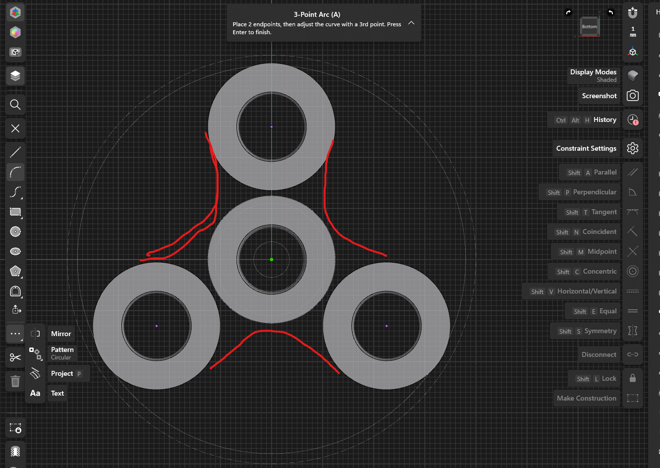 DESIGN IN PROGRESS / The red strokes mark the intended connections between the outer circles in Shapr3D.Shapr3D screenshot and red design marks supplied by Robert Hutchins. Preserved as supplied. Red strokes show intended connections rather than finished CAD geometry.
TECHNICAL NOTES///
A three-lobed spinner, four bearings, and a lesson in keeping the mechanism simple. Shapr3D modeling notes, a magnetic detour, the finished print, and the original STL.
The theme for this build is simplicity wins. A small printed mechanism gave me a reason to learn a few CAD controls, question the bearing resistance, and follow a tempting magnetic idea far enough to understand its limits.
First, make the material join. In Shapr3D I wanted to extrude a circle downward to create a connection, but the operation was subtracting material. The useful control was the Boolean badge beside the extrusion distance: choose Union when the intent is to add the extrusion to the existing body. It was a small interface detail with a large effect on what the model became.
Then make the circles feel like one shape. The sketch had a central ring and three rings around it. I marked the connections I wanted in red: inward curves between the outer circles. The advice was to start with a 3-Point Arc, keep each endpoint coincident with its circle, and make the arc tangent to both circles. Coincident keeps the endpoint attached; tangent makes the transition smooth. The endpoints need room to slide while those constraints solve. Those notes explain the approach discussed, while the screenshot preserves the shape I was aiming for.
The bearings raised another question. The new bearings felt a little stiff, so I asked whether WD-40 would help. The discussion redirected attention to the source of the drag: grease, seals, an overly tight printed pocket, or a surface rubbing after assembly. A useful check is to compare the bearing before and after fitting it. The conversation did not establish that I changed the lubricant or measure how much resistance came from the housing.
Then came the magnetic detour. What if N52 magnets sat in pockets around a PLA bearing housing? I wanted the spin to last longer, and magnets snapping together or pushing apart made it feel as though there ought to be something useful there. The discussion separated a magnetic push from a continuing source of energy: a fixed arrangement may help during one part of the rotation and resist during another. Resetting an attracting or repelling arrangement takes energy. Simply arranging magnets around a bearing does not supply a new push on every revolution.
There was still an interesting experiment to keep. Magnets can support some of a rotor's load in a suitable arrangement, reducing what the bearing has to carry. That is different from expecting a steel bearing to repel a magnet, or expecting magnets fixed inside one housing to drive that same housing around. A removable magnet setup and repeated comparisons were suggested. No such comparison is documented here, so the magnetic idea remains a question for another test.
Back on the workbench, the result is straightforward: a white printed body, three rounded lobes, and four bearings. The photo gives the CAD discussion a physical ending. The STL keeps the shape available for the next attempt. Simplicity wins here because the project has reached an object I can hold and examine; the more elaborate ideas can wait until there is a useful measurement to compare them against.
DEVELOPMENT HISTORY///
Brought together the extrusion and bearing discussion, the magnet experiment discussion, and the connecting-arc sketch as one build story. Added the supplied photograph and original STL.
SPECIFICATION///
RELEASED MATERIAL///
A printed spinner with four installed bearings is documented in the supplied photograph. The original model is available below. Spin duration, bearing fit tolerances, and any benefit from magnets have not been measured in this record.
The record keeps what is known at this revision. Unfinished tests stay unfinished here.