Scan mesh to editable SOLIDWORKS model
Reconstruct useful design intent instead of treating every triangle as a separate CAD face.
Build features around the mesh
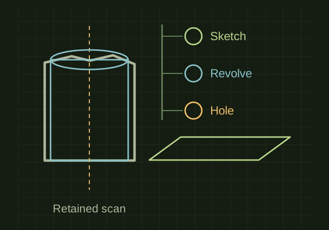 OPEN FULL SIZE ↗
- Fit
- Planes, cylinders and sections
- Retain
- Unmodified mesh for comparison
- Mark
- Inferred hidden geometry
TECHNICAL NOTES///
Reconstruct useful design intent instead of treating every triangle as a separate CAD face.
GOALRun the first test described in this guide and record the result for scan mesh to editable solidworks model.
EQUIPMENT
- Scanner / mesh workflow
- Representative test model
- Measurement or inspection method
STEPS
- Import the mesh with correct units, trim irrelevant data and align it to functional datums.
- Measure and fit primary planes, cylinders and section curves while retaining the unmodified mesh for comparison.
- Build sketches, extrusions, revolves, holes and surfaces in a logical feature tree. Use licensed reverse-engineering tools where available.
- Compare the reconstruction to the mesh and independent dimensions, then export both native and neutral formats as agreed.
TROUBLESHOOTING
- A faceted solid conversion is not the same as a clean parametric model. Smoothing can erase wear or functional edges. Mark inferred hidden geometry explicitly.
THINGS TO WATCH FOR
A faceted solid conversion is not the same as a clean parametric model. Smoothing can erase wear or functional edges. Mark inferred hidden geometry explicitly.
RESULTThe model rebuilds after a controlled parameter change and still meets the checked interfaces.
DEVELOPMENT HISTORY///
Imported as an independent manifest record; public copy keeps uncertainty visible.
Connected the newer project records: MDL-ICE-SHOVEL-001, MDL-GNOME-001. Existing test limitations remain in place.
SPECIFICATION///
RELEASED MATERIAL///
The model rebuilds after a controlled parameter change and still meets the checked interfaces.
The record keeps what is known at this revision. Unfinished tests stay unfinished here.