Structural dimension applicators
Apply dimensions according to member geometry and a defined detailing convention. Work on a copy first. Record application version, units and active document/configuration. Names below identify the catalogued workflow; they do not claim a particular button layout or verified implementation.
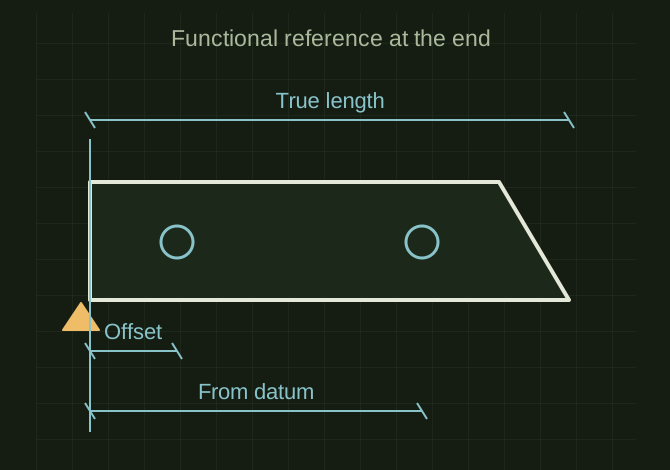
Dimension from the functional references
 OPEN FULL SIZE ↗
- References
- Functional datums
- Details
- Length, cuts and holes
- Avoid
- Redundant closed dimension chains
TECHNICAL NOTES///
Apply dimensions according to member geometry and a defined detailing convention.
GOALRun the first test described in this guide and record the result for structural dimension applicators.
PREPARATION / NOTES
Work on a copy first. Record application version, units and active document/configuration. Names below identify the catalogued workflow; they do not claim a particular button layout or verified implementation.
EQUIPMENT
- CAD / automation tool
- Representative test model
- Measurement or inspection method
STEPS
- Identify the section type and the drawing view’s orientation.
- Select functional datums and dimension overall length, cuts and relevant hole locations from those references.
- Use the approved convention for miters, copes and sloped ends, avoiding redundant closed dimension chains.
- Review extension-line attachment and legibility after a model change.
TROUBLESHOOTING
- A projected view length may not be the true member length. Automatically selecting the longest visible edge can misidentify a coped or mitered part.
SAFETY / LIMITS
- Use qualified judgment and current manufacturer or code guidance for safety-critical work.
THINGS TO WATCH FOR
A projected view length may not be the true member length. Automatically selecting the longest visible edge can misidentify a coped or mitered part.
RESULTDimensions stay attached to the intended features and describe the actual manufactured member.
DEVELOPMENT HISTORY///
Imported as an independent manifest record; public copy keeps uncertainty visible.
SPECIFICATION///
RELEASED MATERIAL///
Dimensions stay attached to the intended features and describe the actual manufactured member.
The record keeps what is known at this revision. Unfinished tests stay unfinished here.