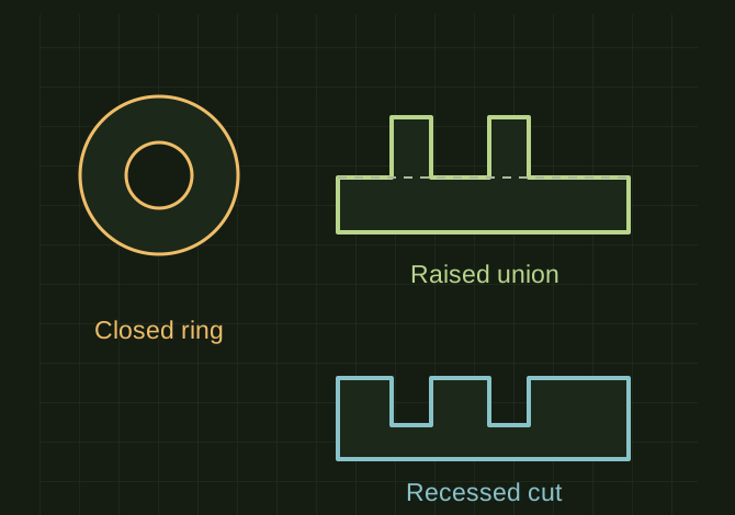
Turn the black regions into closed profiles before using them to add or remove material.
PUBLIC KNOWLEDGE VIEWCAD / Scanning / Automation / how-to
SOURCE STATENew reference guidance; not a recovered test result
GOALRun the first test described in this guide and record the result for cutting/embossing traced black artwork.
EQUIPMENT
CAD / automation tool
Representative test model
Measurement or inspection method
STEPS
Trace or import clean vector outlines and confirm which enclosed regions represent solid artwork.
Scale against a known length and remove duplicate or open segments.
Select closed regions and extrude to join for raised art or subtract for engraving. As an FDM sample, try 0.6–1 mm relief and features wider than a single extrusion line.
Print a small detail coupon and adjust narrow strokes or depth before the final part.
TROUBLESHOOTING
Bitmap black areas do not become solid geometry automatically. Counters inside letters must remain holes. Cutting through a thin base can detach the artwork.
THINGS TO WATCH FOR
Bitmap black areas do not become solid geometry automatically. Counters inside letters must remain holes. Cutting through a thin base can detach the artwork.
RESULTThe slicer shows all intended strokes and islands, and the sample remains readable at final size.
 OPEN FULL SIZE ↗