Parallel second-edge offset for hole patterns
Use two parallel edges to define row placement without confusing edge direction and distance. Work on a copy first. Record application version, units and active document/configuration. Names below identify the catalogued workflow; they do not claim a particular button layout or verified implementation.
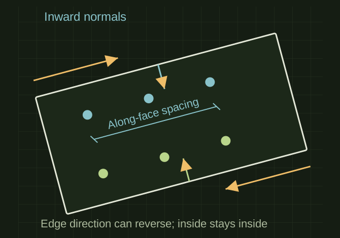
Offset inward from two parallel edges
 OPEN FULL SIZE ↗
- References
- Two straight parallel edges
- Distances
- Signed normal offsets
- Preview
- Inside-face centers and margins
TECHNICAL NOTES///
Use two parallel edges to define row placement without confusing edge direction and distance.
GOALRun the first test described in this guide and record the result for parallel second-edge offset for hole patterns.
PREPARATION / NOTES
Work on a copy first. Record application version, units and active document/configuration. Names below identify the catalogued workflow; they do not claim a particular button layout or verified implementation.
EQUIPMENT
- CAD / automation tool
- Representative test model
- Measurement or inspection method
STEPS
- Select the face and two straight reference edges, then express them in the same sketch coordinate system.
- Verify parallelism within a stated tolerance and reject ambiguous or coincident choices.
- Define the inward normal and signed distances; constrain the first row from one edge and the second from the other.
- Preview all centers, checking inside-face placement and minimum edge distance before creating holes.
TROUBLESHOOTING
- Reversed edge parameter direction can flip an offset. A bounding-box distance is not the true normal distance for a rotated part.
THINGS TO WATCH FOR
Reversed edge parameter direction can flip an offset. A bounding-box distance is not the true normal distance for a rotated part.
RESULTRotate the model and reverse selection order in a test copy; the intended physical rows remain correct.
DEVELOPMENT HISTORY///
Imported as an independent manifest record; public copy keeps uncertainty visible.
SPECIFICATION///
RELEASED MATERIAL///
Rotate the model and reverse selection order in a test copy; the intended physical rows remain correct.
The record keeps what is known at this revision. Unfinished tests stay unfinished here.