Inventor iLogic rule 023 selectable-face hole pattern
Define a hole pattern from an explicitly selected planar face and meaningful edge references. Work on a copy first. Record application version, units and active document/configuration. Names below identify the catalogued workflow; they do not claim a particular button layout or verified implementation.
The hole pattern belongs to the selected face
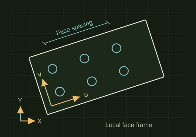 OPEN FULL SIZE ↗
- Validate
- Planar selected face
- Place
- Constrained offsets and spacing
- Test
- Second face orientation
TECHNICAL NOTES///
Define a hole pattern from an explicitly selected planar face and meaningful edge references.
GOALRun the first test described in this guide and record the result for inventor ilogic rule 023 selectable-face hole pattern.
PREPARATION / NOTES
Work on a copy first. Record application version, units and active document/configuration. Names below identify the catalogued workflow; they do not claim a particular button layout or verified implementation.
EQUIPMENT
- Inventor / iLogic
- Representative test model
- Measurement or inspection method
STEPS
- Validate a part document and planar face selection; handle user cancellation before starting an edit.
- Create a sketch in the face coordinate system and project the required reference edges.
- Place hole centers using constrained offsets and spacing, with explicit units and edge clearances.
- Create the intended hole feature, update the document and commit only if the expected holes are present.
TROUBLESHOOTING
- Model-space coordinates and sketch-space coordinates differ. A circular or curved edge may not define the intended offset direction. Do not assume the original rule 023 code was recovered.
THINGS TO WATCH FOR
Model-space coordinates and sketch-space coordinates differ. A circular or curved edge may not define the intended offset direction. Do not assume the original rule 023 code was recovered.
RESULTA second face orientation produces the same intended relative pattern without mirrored or off-face holes.
DEVELOPMENT HISTORY///
Imported as an independent manifest record; public copy keeps uncertainty visible.
SPECIFICATION///
RELEASED MATERIAL///
A second face orientation produces the same intended relative pattern without mirrored or off-face holes.
The record keeps what is known at this revision. Unfinished tests stay unfinished here.