Thread gauge STL file
A conversation-specific public summary of thread gauge stl file, distilled from the supplied export. The detailed excerpts remain available in the released note file.
Two different ways to identify a thread
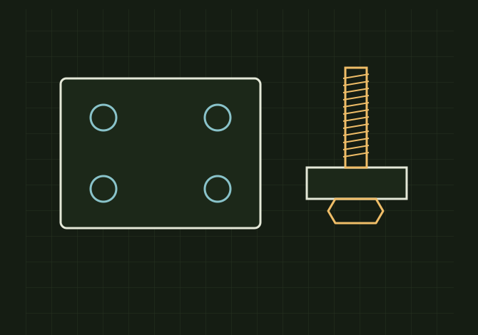 OPEN FULL SIZE ↗
- Pilot side
- 1/4-20, 5/16-18, M6×1.0, M8×1.25
- Stud side
- Captured 1/4-20 bolt
- Wear surface
- Metal threads on the stud
TECHNICAL NOTES///
Conversation-specific knowledge extracted from the thread gauge stl file discussion.
QUESTION / CONTEXTI want a stl file of a thread gauge, on the left half I want to be able to thread bolts into it to verify the threads and on the right side I want approximately an inch of a a threaded bolt sticking up so I can use it to verify nut sizes
IMPORTANT GUIDANCE
- Left side: four pilot holes sized to let you *self-thread* common bolts directly into the plastic (perfect for quick ID): 1/4-20, 5/16-18, M6×1.0, M8×1.25.
- Right side: a captured 1/4-20 metal bolt. You insert a real bolt from the bottom into a hex pocket so the threaded shank (~1") sticks up on top for checking nut sizes (no printed threads to wear out).
- OpenSCAD source (ready to render/export to STL):
- Print the part with the hex pocket facing down.
- Press a 1/4-20 hex bolt up from the bottom; the head will capture in the pocket. If you want the stud locked in, add a nut on top as a jam nut.
- On the left, just drive your bolts into the pilot holes—plastic “cuts” threads for a snug check fit.
- 1/4-20 pilot ≈ 0.201 in (5.11 mm)
- 5/16-18 pilot ≈ 17/64 in (6.75 mm)
Extracted from the conversation’s assistant responses and edited for public clarity. See the released note for additional redacted excerpts.
DEVELOPMENT HISTORY///
Matched to the supplied export; key guidance is surfaced separately and the raw transcript remains unpublished.
SPECIFICATION///
RELEASED MATERIAL///
RECOVERED / SPECIFIC NOTE
The record keeps what is known at this revision. Unfinished tests stay unfinished here.